US12410977 - Firearm
firearmmechanismbreechbarrel
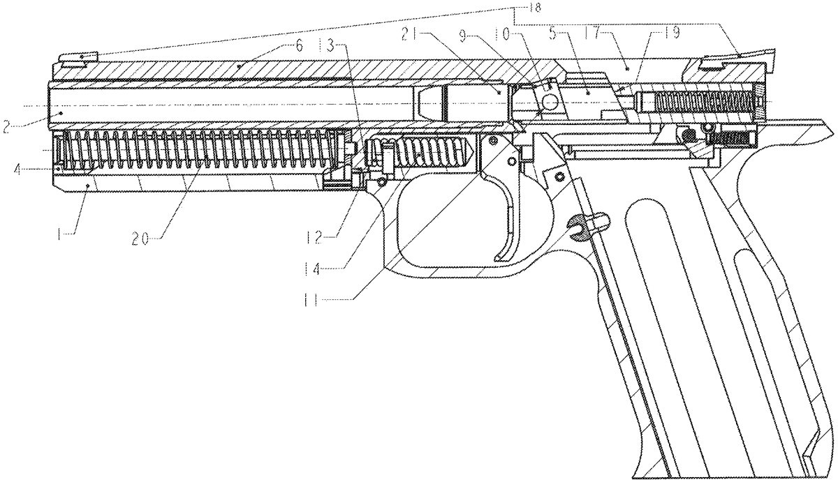
The patent describes a firearm design featuring a frame that accommodates a sliding breech block carrier and a barrel connected to a barrel sleeve, which is also mounted in a linear guide within the frame. It includes a vertically movable locking block that engages with a recess in the barrel sleeve, along with various stops and a barrel spring to enhance functionality and stability.
Claim 1
- A firearm, comprising a frame ( 1 ) in which a breech block carrier ( 4 ) is arranged, as well as a barrel ( 2 ) having a rear face ( 3 ) behind which a breech block ( 5 ) is arranged in the frame ( 1 ), characterized in that the barrel ( 2 ) is firmly connected to a barrel sleeve ( 6 ), and the barrel sleeve ( 6 ) is slidingly mounted in a linear guide in the frame ( 1 ), wherein the breech block ( 5 ) is mounted behind the rear face ( 3 ) of the barrel ( 2 ) slidingly in a direction of a barrel ( 2 ) axis, and the breech block carrier ( 4 ) is slidingly mounted in a linear guide in the frame ( 1 ) wherein on a top side of the breech block ( 5 ), a vertically movable locking block ( 9 ) is arranged, and the locking block ( 9 ) can be introduced into a recess ( 10 ) in the barrel sleeve ( 6 ), wherein the frame ( 1 ) is provided with a front stop ( 12 ) for the barrel sleeve ( 6 ), and a rear stop ( 13 ) for the barrel sleeve ( 6 ), and the barrel sleeve ( 6 ) is provided with a front stop ( 15 ) for the breech block ( 5 ), and a rear stop ( 16 ) for the breech block carrier ( 4 ), wherein a barrel spring ( 14 ) is arranged between the frame ( 1 ) and the barrel sleeve ( 6 ). and the barrel sleeve ( 6 ) is slidingly mounted in a linear guide in the frame ( 1 ), wherein the breech block ( 5 ) is mounted behind the rear face ( 3 ) of the barrel ( 2 ) slidingly in a direction of a barrel ( 2 ) axis, and the breech block carrier ( 4 ) is slidingly mounted in a linear guide in the frame ( 1 ) wherein on a top side of the breech block ( 5 ), a vertically movable locking block ( 9 ) is arranged, and the locking block ( 9 ) can be introduced into a recess ( 10 ) in the barrel sleeve ( 6 ), wherein the frame ( 1 ) is provided with a front stop ( 12 ) for the barrel sleeve ( 6 ), and a rear stop ( 13 ) for the barrel sleeve ( 6 ), and the barrel sleeve ( 6 ) is provided with a front stop ( 15 ) for the breech block ( 5 ), and a rear stop ( 16 ) for the breech block carrier ( 4 ), wherein a barrel spring ( 14 ) is arranged between the frame ( 1 ) and the barrel sleeve ( 6 ).
Google Patents
https://patents.google.com/patent/US12410977
USPTO PDF
https://image-ppubs.uspto.gov/dirsearch-public/print/downloadPdf/12410977