US12296979 - Attack helicopter
firearmammunitionhelicoptermachine_cannon
The patent describes an attack helicopter featuring a body designed for optimal airflow during flight, equipped with a machine cannon and an innovative ammunition duct that runs along a central butt line to facilitate efficient ammunition transfer. This design minimizes mass concentration at any single point and includes multiple rotary actuators and retainers to ensure continuous ammunition delivery to the cannon.
Claim 1
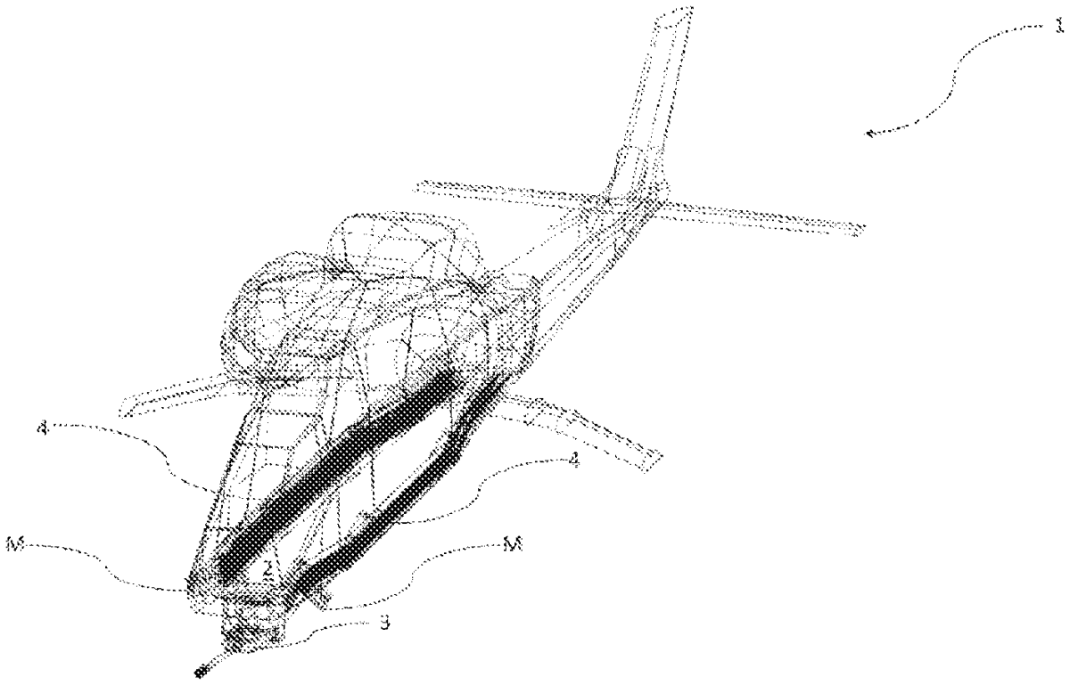
- An attack helicopter ( 1 ) comprising: a body ( 2 ) exposed to air flow during flight of the attack helicopter ( 1 ); at least one ammunition (M) fired to attack a target; at least one machine cannon ( 3 ) enabling the ammunition (M) to be fired; at least one ammunition duct ( 4 ) on the body ( 2 ) and arranged along a butt line (BL) that extends lengthwise on the attack helicopter ( 1 ) and symmetrically divides the attack helicopter ( 1 ) in two, the at least one ammunition duct ( 4 ) enabling the ammunition (M) to be placed therein and the ammunition (M) to be transferred to the machine cannon ( 3 ), wherein the ammunition duct ( 4 ) enables all of the ammunition (M) to be located on the body ( 2 ) and to extend along the direction on which the butt line (BL) extends, prevents the accumulation of ammunition (M) at a single point and thus a high mass at the single point in the body ( 2 ), through allowing each of the ammunition (M) to be transmitted in the same direction one after another and enabling the ammunition (M) to be efficiently placed on the body ( 2 ); more than one rotary actuator ( 5 ) located on the body ( 2 ) so as to be spaced apart from each other and enabling the ammunition (M) to be transmitted uninterruptedly and continuously along the ammunition duct ( 4 ); more than one gear ( 6 ) enabling the drive received from the rotary actuator ( 5 ) to be transmitted; and more than one rotary retainer ( 7 ) located on the body ( 2 ) so as to be spaced apart from each other and to be able to rotate about its own axis and enabling the ammunition (M) to be transmitted by being pushed towards the machine cannon ( 3 ) by means of the drive transmitted from the gear ( 6 ). a body ( 2 ) exposed to air flow during flight of the attack helicopter ( 1 ); at least one ammunition (M) fired to attack a target; at least one machine cannon ( 3 ) enabling the ammunition (M) to be fired; at least one ammunition duct ( 4 ) on the body ( 2 ) and arranged along a butt line (BL) that extends lengthwise on the attack helicopter ( 1 ) and symmetrically divides the attack helicopter ( 1 ) in two, the at least one ammunition duct ( 4 ) enabling the ammunition (M) to be placed therein and the ammunition (M) to be transferred to the machine cannon ( 3 ), wherein the ammunition duct ( 4 ) enables all of the ammunition (M) to be located on the body ( 2 ) and to extend along the direction on which the butt line (BL) extends, prevents the accumulation of ammunition (M) at a single point and thus a high mass at the single point in the body ( 2 ), through allowing each of the ammunition (M) to be transmitted in the same direction one after another and enabling the ammunition (M) to be efficiently placed on the body ( 2 ); more than one rotary actuator ( 5 ) located on the body ( 2 ) so as to be spaced apart from each other and enabling the ammunition (M) to be transmitted uninterruptedly and continuously along the ammunition duct ( 4 ); more than one gear ( 6 ) enabling the drive received from the rotary actuator ( 5 ) to be transmitted; and more than one rotary retainer ( 7 ) located on the body ( 2 ) so as to be spaced apart from each other and to be able to rotate about its own axis and enabling the ammunition (M) to be transmitted by being pushed towards the machine cannon ( 3 ) by means of the drive transmitted from the gear ( 6 ).
Google Patents
https://patents.google.com/patent/US12296979
USPTO PDF
https://image-ppubs.uspto.gov/dirsearch-public/print/downloadPdf/12296979